Digital IO Board 2 Relays (DIO-002)

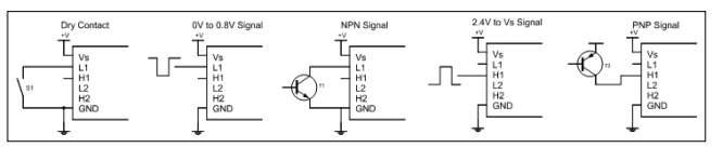
The DIO-002 digital IO board is designed to allow easy integration of relays to existing hardware. The board lets you switch high voltage or high current loads from Lab Jack modules, PLCs, microcontrollers and logic circuitry. The relays mounted on the board have the following specifications:

Rated Load 10A/250VAC, 10A/24VDC
Contact Resistance 50 mΩ
Dielectric Strength Between Contacts and Coil >5000 VAC / minute
Operation Time < 10 ms
Reset Time <5 ms
Reseller Enquiries
  • 1.5 mm wide isolation slots and a large 14 mm creepage distance between the coil and contact side provide high levels of isolation and protection and allow low voltage circuitry to switch AC power safely.
  • The driver circuitry has high and low inputs for interfacing to a wide range of equipment.
  • Dry contact (buttons, switches, other relays), NPN-type outputs, push-pull type outputs and active-low signals connect to the relay card’s Low inputs.
  • PNP-type outputs, push-pull type outputs and active-high signals connect to the relay card’s High inputs.
  • A relay is triggered if the Low input is pulled below approximately 0.8 V, or if the High input is pulled above approximately 2.4 V.
  • Voltage at either input should not be driven below 0 V or above the supply voltage 12 V.
  • The circuitry for relay draws approximately 2 mA while deactivated and approximately 32 mA when the relay is active. 

Wiring:

Connection of terminal blocks

The connection sequence should be accurate.  Cable’s insulating striping length is about 7mm.  The power cable should be connected correctly.  Please double check before switching the router on.  Wrong connections may destroy the equipment.

Modem Relay board
VCC to VS
GND to GND
DIO0 to H1
DIO1 to H2

Get in Touch With Sales