

The DIO-001 is a multipurpose digital IO board specifically designed for the CM685 router. To install the DIO-001, you need 4 PCB standoffs to support the board. Detachable screw terminals are provided for quick connection of all wires between the DIO board and the router. Each block of screw terminals can be detached for easy replacement of the board if required. The DIO-001 requires 12VDC to operate properly. The power supply can be the same as the CM685 router.

Parts & Accessories
The DIO-001 features 1 switching contact with 1 normally-closed output (R0,L0) and 1 normally-open output (R1,L1). Maximum loads are 5A at 30VDC and 5A at 240VAC.
Connection of terminal blocks
The connection sequence should be accurate. The cable insulating striping length is about 7mm. The power cable should be connected correctly. Please double check before switching the router on. Wrong connections may destroy the equipment.
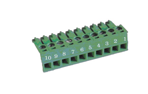
| PIN | Signal | Description | Note |
| 1 | VCC | +5-40V DC Input | Current:12V/1A |
| 2 | GND | Ground | |
| 3 | TX | Transmit Data | |
| 4 | RX | Receive Data | |
| 5 | PGND | Ground | |
| 6 | RST | Reset |
Reset Pin has the same function as the reset button. To use it, it needs to be connected to the GND. After giving the device a 1 sec low level, it will reboot. At 3 seconds, the device will restore the factory settings |
| 7 | DIO0 | General Purpose I/O | |
| 8 | DIO1 | General Purpose I/O | |
| 9 | NC | Not connect |